How To Replace A Wall Switch Step-By-Step
We may receive a commission on purchases made from links.
Replacing a wall switch ought to be as simple as putting a new one in, wired the same way the old one was. It seems pretty simple. Even DIYers who steer clear of electricity are willing to occasionally swap out a light switch, but things have gotten complicated. Say, for example, your spouse buys you a Yogi Berra light switch cover plate that features an integrated night light. As Yogi Berra might have said, it's not necessarily as simple as it used to be, and it probably never was.
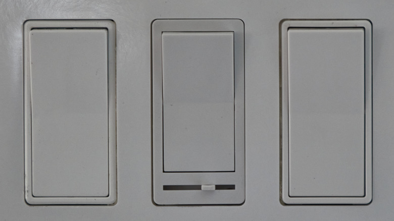
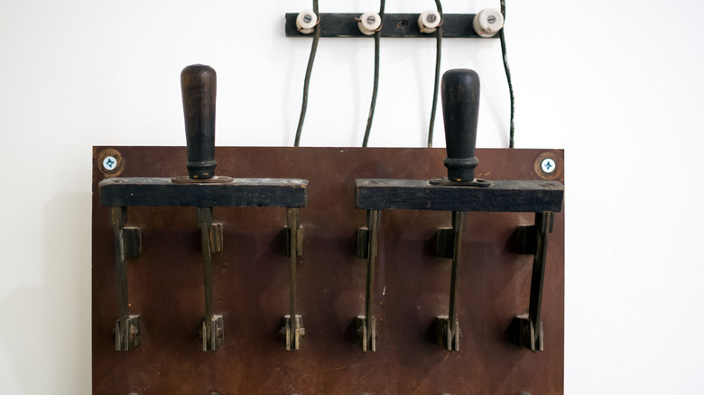
There are different styles of simple switch, various types of dimmer, fan speed controllers that look like (but aren't) dimmers, two-pole switches, three- and four-way switches, switches with integrated doodads, smart switches of every imaginable sort (and a few that are still hard to imagine), and heaven knows what else, according to Home Decor Bliss. They don't even all look the same; some are rocker-style paddle or Decora switches, while older ones are mostly toggle switches, which is what anyone over 40 pictures when you say "light switch." And a few simply aren't visible at all, being controlled by wifi or other electronic wizardry.
Oh, and they don't necessarily control lights, but we'll refer to them as light switches to keep things readable.
First things: tools and safety
You'll need some tools, and as always it's best to gather these up front. You'll need a screwdriver or drill driver. While you can get by with a #2 Phillips driver or bit, or even a slotted bit, do yourself a favor and find a Robertson #1 square drive. Or you could invest in a set of expensive Milwaukee ECX screwdrivers with a unique bit shape made for wiring electrical devices, says Everyday Home Repairs. (They're $21.97 for the set at Home Depot. "A nickel ain't worth a dime anymore," Yogi Berra once said, according to Parade.) Klein and Southwire combination tip bits are similar. The reason for all this comes down to torque. Securing wires to electrical devices like switches can require quite a lot of torque. Without it, you will have loose connections, or possibly no connection at all, and therefore an electrical short waiting to happen.
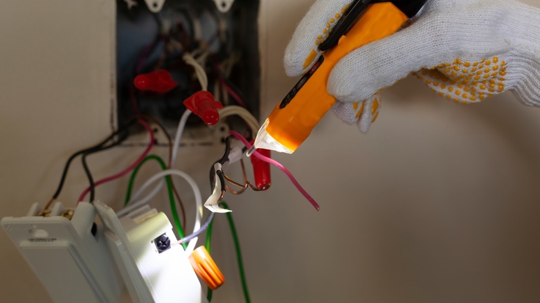
You're going to also need a contactless voltage tester. There are two basic types: solid state testers and solenoid testers. Solid state testers are somewhat safer than the solenoid models because the solid state versions use a circuit specifically designed to handle failures, while solenoid testers fail in less predictable ways that can include catastrophic and dangerous mechanical failure (via Fluke, who manufactures both types of device). While the models listed by Fluke can cost over $300, perfectly reliable non-contact testers are available for less than $10 (via Home Depot).
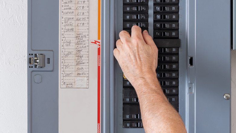
You might also need needle-nose pliers, wire strippers, wire nuts (or similar), and a flashlight. After gathering all your tools, the first thing is to turn off the circuit breaker that feeds the switch you're replacing, so you'll need that flashlight sooner rather than later. Stick tape over the circuit breaker switch so no one accidentally turns it back on while you're working. This does happen.
Removing the old switch
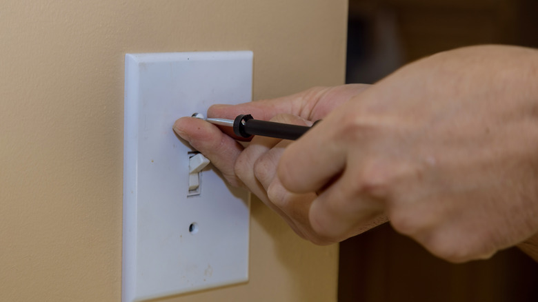
Start by turning on your flashlight, if you can find it in the dark. ("It's too dark in here to see if the power is on," Yogi Berra might have said.) Start by removing the cover plate. (Here you'll probably need a slotted screwdriver or bit. Electrical devices employ slotted screws more commonly than just about any other equipment.) Next, use your voltage tester to confirm that the power is, indeed, off to your switch. Don't have a circuit tester? Put the cover plate back on and get one. Electricity ain't nothing to mess with.
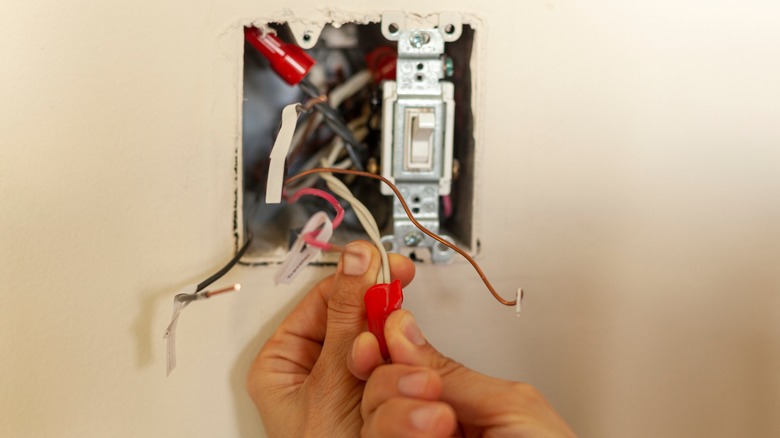
After your tester confirms the electrical box isn't powered, remove the screws holding the old switch in place, then pull it gently away from the box so you can get to all sides of the device. Note which wires are connected to which terminals; it's a good idea to take a photo for reference, especially if you're replacing a three- or four-way switch. (More on that later.) If you see paint or marker, or tape wrapped around any of the wires, note it; this means a wire has been re-identified so that its original insulation color no longer correctly identifies its purpose. A white (usually neutral) wire is often marked black with paint or tape when it's serving as a hot. You'll want to keep those markings in place when re-installing the wire (via Electrical Construction & Maintenance).
Disconnect the wires. If any of the wires are inserted in holes in the back of the switch (called "backstabs" by electricians), you can insert a small flathead screwdriver in a slot near the hole to open the connection so that you can pull the wire out. If you're concerned about getting the wires confused, you can disconnect them and connect to the new device one at a time to help keep things straight.
Switch wiring basics
Before you start reconnecting things, let's take a minute to go over the most basic information about switch wiring conventions. Like Yogi says, "You've got to be very careful if you don't know where you are going, because you might not get there." This will help you to spot problems before they're really problems. It gets complicated even for simple two-way (on/off) switches because there are a number of ways a light switch can be wired. If your hot wire comes in at the switch, you will likely have two black wires (and a ground, if present) connected to your switch. If power enters at the lighting fixture itself, you will likely connect both black and white (marked with black tape) wires to your switch, per How To Wire It.
Usually screw terminal color relates to the function of the wire you're attaching to it: white (neutral) connects to a silver terminal, black (hot) connects to a brass screw, and green or bare copper connects to a green ground screw. Basic switches don't use the neutral, and so have two brass terminals. You might find that your switch connects to two neutral wires instead of two hots... the light is switched on the neutral wire rather than the hot. If so, stop and call an electrician, because this creates a dangerous potential for electrocution at the light fixture itself.
Typically all the ground wires that enter a switch's box are connected together with a wire nut or similar device, with a short "pigtail" wire attached to the switch. The same is true for neutral wires, except that there's no pigtail as there's no need to connect neutral to simple light switches. Consult the diagrams on John Grabowski's Mr. Electrician site for more help finding out where you are and where you're trying to go.
Connecting the new switch
Putting everything back together is pretty straightforward. When you're connecting the wires to your new basic on/off switch, you will have three options: for the cheapest switches, wrap each wire around a screw terminal; for some higher-end switches, secure the wires under a pressure plate that is tightened down by the terminal screw; and using the backstab holes in the device to secure your wires.
First, let's rule out the last option. Backstabs are notoriously insecure (and therefore dangerous) over the long haul, says George Brazil, and they don't typically accept 12-gauge wire, which is increasingly common in houses as 20 amp circuits are required by code in more and more places. So it's best to avoid backstabs altogether.
If a pressure plate is available, make sure your stripped wire ends are straight and no longer than the stripping guide on the back of the switch, then secure the wire under the plate and tighten the screw well.
For securing wire under simple screw terminals, you'll need to bend the wire into a hook shape using needle-nose pliers (or the holes in the side of most electrician's wire-stripping pliers). Hook this loop around your screw with the insulation end on the left (looking down at the head of the screw) and the wire's end on the right, so that you won't inadvertently loosen the wire when tightening the screw. Once the wires are attached, it's a good idea to wrap the switch in electrical tape so that the wires and terminals don't make accidental contact with other wires.
From here, you'll just do everything from earlier in reverse. "It's deja vu all over again," as Yogi said. Fold the wires back into the box. Push the switch into place and secure with its screws, screw on the cover plate, turn on the circuit breaker, and check that everything is working properly (via Mr. Electrician).
Three-way switches
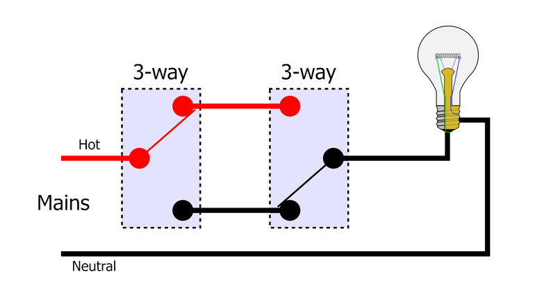
In staircases and rooms with multiple entrances, you will often find multiple switches that control a single light. If there are two such switches, they're called a three-way switch, says Price Electric. Here's how the most common arrangement is wired, though there are a lot of possible arrangements so you'll need to study your situation closely. "If the world were perfect, it wouldn't be," Yogi once said.
The wiring for three-way switches isn't completely intuitive. It usually works like this: a two-wire-plus-ground cable (12/2 or 14/2 with black, white, and bare wires) runs from the power source to your first switch. Connect the black (hot) wire to the terminal marked "common" (usually a black screw).
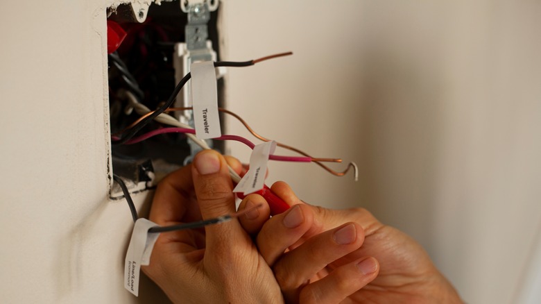
A three-wire-plus-ground (12/3 or 14/3 with black, usually red, white, bare) cable runs from the first switch to the second. At the first switch, connect the black wire to one of the brass traveler screws, and red to the other. Use a wire nut or similar to connect the white wire to the loose white wire from the first cable and fold the wire into the back of the box. Use a wire nut to connect the bare copper ground wires to each other and to an additional pigtail, and attach the pigtail to the switch's ground terminal (green). Push the bundled bare wires into the back of the box.
At the other switch, connect the black and red wires to the two brass traveler screws. Another two-wire-plus-ground cable (12/2 or 14/2) runs from the second switch to the light fixture. In the second switch box, connect its black wire to the common terminal, then connect the white and bare wires exactly as you did in the first switch box.
At the lighting fixture, connect the black wire to positive, the white wire to negative, and the ground to ground (via Build My Own Cabin).
Four-way switches
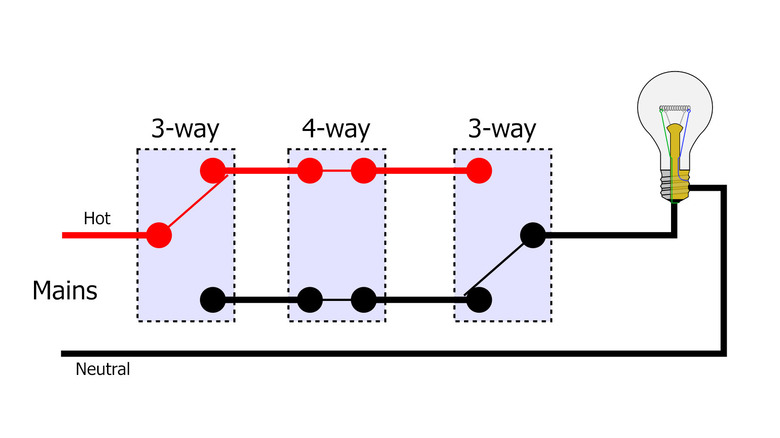
Four-way switches are used when you have at least three switches controlling one light. For a three-switch setup, you will have two three-way switches and one four-way switch. The trick is figuring out which one is which. As Yogi said, "You can observe a lot by just watching." Look carefully before you remove wires from the old switch, and take notes and pictures as needed.
The Mr. Electrician diagrams are particularly useful for understanding four-way switch wiring, and Rick Matthews has a great tutorial on the Wake Forest University site that's helpful for understanding how three- and four-way switches actually work. Using the same arrangement as we did for the three-way switch above, the ends of the four-way switch system are identical. That is, the circuit breaker side and the lighting fixture side are wired exactly the same. To add a switch, you'd put a four-way switch between the three-way switches. On each side, use a three-wire-plus-ground cable (12/3 or 14/3) to connect the three-way switch to the new four-way switch (red to traveler, black to traveler, ground to bundled ground and switch, white to bundled white).
Then you can add any number of additional (four-way) switches to the middle of this arrangement using the same cable and method.
Other possibilities for three- and four-way switches
There are many other possible arrangements of three- and four-way switches. In a two-switch circuit, for example, you might have the lighting fixture at any point between the two three-way switches rather than at one end as discussed above. You could also have the line (hot from breaker box) and load (neutral from lighting fixture) wires inside the same switch box with either three- or four-way setups.
There are also some arrangements in which you can use a two-wire-plus-ground cable (12/2 or 14/2). This requires re-identifying and re-labeling any white wire that shifts purpose from a neutral to a hot ungrounded conductor.
Diagrams provided in your switch packaging will be very useful, since labeling and terminology vary by manufacturer, says John Grabowski (via Mr. Electrician). Terminology and wire color schemes also vary overseas. In the U.K. for example, a three-way switch is called a two-way switch and the terminals are labeled Common, L1 and L2.
Dimmers and fan speed controllers
Most dimmers are pretty simple to replace. They usually come with color-coded wires already attached and function basically like switches. All a dimmer is usually doing is controlling the voltage to the light. So wiring a switch that contains a dimmer mechanism would be reasonably straightforward, a simple one-to-one swap out of wires with the old dimmer or switch, if it weren't for fans.
It's always important to identify a fan circuit properly. Asked if fans running nude across the baseball field were men or women, Yogi Berra once said, "I don't know. They had bags over their heads." It's even worse with electrical wiring, since dimmers don't work properly with fans but look nearly identical to fan speed controllers... not to mention the fact that there are several different types of dimmer to contend with. But if you're replacing a dimmer or fan speed controller, what you really have to do is be sure that you're installing a new device that has the same purpose and requirements as the old one: a two-way dimmer, for example, will have different wiring requirements than a three-way dimmer. The purpose of the device is usually printed on the device itself, so look for language like "fan speed controller," "fan only," or "incandescent fixtures only" (via Smart Home Starter). If you're unsure, consult your retailer or an electrician. And under no circumstances try to control both a fan and dimmable lights with a single dimmer. It might work, but only until the fire starts.
If you need help wiring a dimmer, try Lutron's Wiring Wizard. It covers a lot of the complexities of dimmer installation by asking a series of simple questions to narrow down your situation. "When you come to a fork in the road, take it," as Yogi said.
Switches with no neutral or no ground
At first blush, it seems very strange that an electrical box wouldn't include a neutral, but this is normal in certain switch wiring layouts because all that is required to operate and even dim most lights is the hot conductor. If a neutral is present, it is merely passed through without changing anything. But modern smart switches often require a neutral wire, and some even require a ground. ("The future ain't what it used to be," Yogi Berra said.) This can obviously be a problem if your home was wired without a ground, or if that particular switch doesn't have a neutral wire.
Grounds are easy, or at least simple. If your circuit doesn't have a ground but your switched device does, connect the ground wire from the device to the switch. If your switch has a metal box and it's grounded, this will take care of grounding the device too, according to David L. Farquhar of The Silicon Underground. And if your switch doesn't have a ground terminal, replace it with one that does. Of course, your best bet is to get your home wiring grounded properly, and you'll need to call an electrician for that.
A neutral can be added by extending a neutral from a nearby box on the same circuit, or new wiring can be run to your switch. Either of these will probably involve the services of an electrician. A better bet might be to choose a device that doesn't require a neutral, or opt for a smart bulb instead (via Upgraded Home).
Oddities
Let's take a quick look at some oddities in the universe of wall switches. None of these are exactly rare, but they're all relatively uncommon compared to the switches we dealt with above. If you encounter any of these, you'll want to seek additional information about replacing the switch in question.
The double-pole switch, which is literally two separate switches connected to one mechanism. These are easy to spot because they have two cables with hot wires entering the box from different circuit breakers. Remember to turn both off!
As we've said, switches don't always control lights. Sometimes they control receptacles. You often see this in homes where a lamp can be turned on with a switch. A receptacle, or half of a receptacle, is wired like a light so that you can control it from a distance, usually from a doorway.
Some devices combine a switch and a receptacle in one device. These might be duplex devices with a switched outlet, combination switch/outlet devices in which the switch doesn't control the receptacle, or a GFCI combination receptacle that protects against shorts to ground.